
Engineering 24 V and 48 V Drive Trains for AGVs and AMRs: A Practical Build Guide
By Michael Torres, WorldIndustrialWeekly
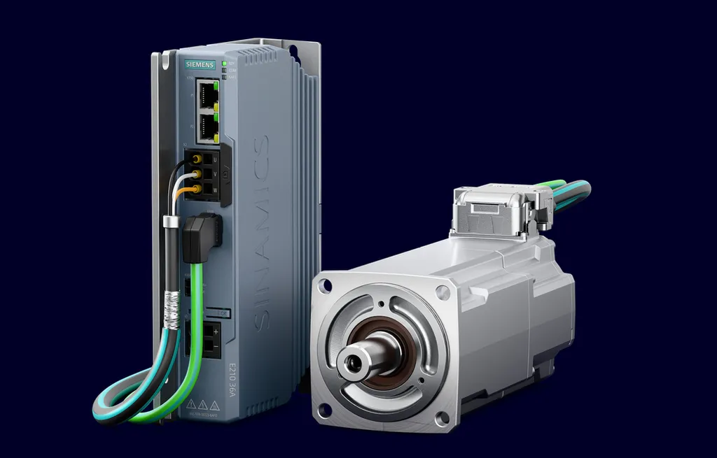
Mobile-robot programmes rarely stall because the navigation stack underperformed. They stall on unglamorous decisions taken too late: a battery architecture that cannot carry a second axis, a braking-energy path nobody modelled, a safety case drafted after the wiring drawing was frozen. That is the working context behind the Siemens entry into the extra-low-voltage (ELV) band for wheeled platforms, pairing the Sinamics E210 converter with the Simotics E-1EE1 servomotors for vehicles powered from 24 V and 48 V packs. Read as a specification rather than as a press item, the combination changes three things for a design team: the conversion stage between battery and drive disappears, the safety channel moves into the motor-and-drive hardware, and the toolchain stops being a patchwork. The rest of this guide is about sequencing the engineering around those three changes — and about the traps that consume weeks.
Why this hardware tier appeared now
Demand data explains the timing better than any product brochure. The Association for Advancing Automation (A3) reported that North American companies ordered 10,989 robots valued at $723.5 million in the third quarter of 2026, a 24.8% rise in units year over year, with roughly $1.89 billion of orders accumulated over the first three quarters. On the deployment side, market researcher Interact Analysis projects the number of order-fulfilment sites running mobile robots to more than triple, from 5,500 in 2024 to 18,000 by 2030. More sites means more vehicles per site, more stop-start cycles per shift and more functions bolted onto each chassis — powered lifts, rotating consoles, conveyor sections, auxiliary pumps.
Each added function is another axis and another cable, and the cheapest place to absorb them is the voltage band that plant electricians, insurers and machine-safety assessors question least. Under IEC 61140, extra-low voltage covers ripple-free direct current up to 120 V, so both 24 V and 48 V platforms sit inside ELV practice, with all the protective-separation and touch-voltage consequences that implies. An integrated ELV drive train therefore sells on programme risk as much as on efficiency.
Reading the pairing as two design objects
Split the announcement into its halves before you put either into a bill of materials.
| Design question | Sinamics E210 | Simotics E-1EE1 |
|---|---|---|
| Primary role | Compact regenerative converter driving traction and wheel drives, plus steering, lifting and auxiliary axes | Servo motor family matched to the converter, extending the ELV range to higher power and torque |
| Power feed | Direct connection to 24 V and 48 V battery systems, so no additional voltage conversion is required | Same ELV battery systems, 24 V and 48 V |
| Mechanical envelope | Compact housing with flexible mounting options for tight chassis packaging | Shaft heights 40 to 63 |
| Safety architecture | Integrated safety functions, PROFIsafe support, PROFINET IRT real-time communication | Absolute 14-bit BiSS-C safety encoder and dual-channel internal design, supporting safety-related duty up to SIL 2 |
| Engineering path | Works with TIA Portal and the Simove modular system | Electronic nameplate lets the converter read motor data automatically during parameterization |
| Variants for vehicle design | High overload capability for transient traction loads | Optional holding brakes, gearbox variants and connection options |
The practical translation is straightforward. Removing a conversion stage removes loss, heat, enclosure volume and a failure mode; the regenerative path returns braking energy to the pack instead of burning it in a resistor, which is where the efficiency claim actually lives on a vehicle that accelerates and stops hundreds of times per shift. Bringing the safety encoder and the safety communication profile into the drive train means the safety concept can be documented against hardware properties rather than against a bolt-on relay box. That is also why the pairing matters for scalable designs facing future automation, safety and cybersecurity requirements: the integration work moves from bespoke wiring to configuration.
A seven-step implementation sequence
- Freeze the duty profile before the drivetrain. Log one representative shift per vehicle type: distance, inclines, dock-plate crossings, mass carried, number of accelerations and stops, and the dwell time of every powered accessory. Drivetrain selection derived from a datasheet instead of a log is the most common cause of a second prototype.
- Build an energy and regeneration budget. Separate energy consumed from energy returned. On vehicles with a lifting axis or a ramp duty, the return flow at deceleration can exceed what a nearly full pack will absorb, so decide early whether the battery acceptance window, the converter's regenerative capability or a dissipation path carries the margin.
- Choose the voltage band against peak power, not nameplate energy. A 24 V architecture stays attractive while the chassis needs only traction; the moment a second or third axis joins, peak current climbs and cable mass climbs with it. Published pack data is useful calibration here: Inventus Power's LV-24V50, launched on 28 October 2026 for AMRs and AGVs, is rated at 1.2 kWh with peak power close to 5 kW and 48 Ah — a fair picture of where a 24 V platform tops out.
- Map every axis to a safety function. Traction, steering, lifting and auxiliary axes each need their stop, speed-monitoring and torque-limit requirement stated on the drawing, with the safety-related level recorded per channel. Anything above SIL 1 belongs in the architecture review, not in the commissioning notes.
- Design the network and the safe data path together. Real-time motion and safe telegram traffic travel over the same physical plant: plan switches, cycle time, wireless handover zones and cable routing at the prototype stage, since PROFINET IRT and PROFIsafe behave very differently on a moving vehicle than on a bench.
- Engineer once, then reuse. Consolidate parameter sets, safety configuration and diagnostics in TIA Portal and build the vehicle logic on the Simove modular system so that portfolio variants become parameter changes instead of redesigns. The electronic nameplate reading motor data automatically is exactly the kind of feature that should be exploited in the first commissioning run, not the tenth.
- Validate against the vehicle standard, not the component certificate. Type-C safety requirements for driverless industrial trucks are set out in ISO 3691-4:2023, and drive-system safety functions such as safe torque off are defined in IEC 61800-5-2. Keep the risk assessment, stopping-distance measurement, speed-monitoring proof and functional-safety test records as one package.
Where 24 V stops and 48 V starts
| Vehicle pattern | Axes and duty | Band that usually fits | Engineering consequence |
|---|---|---|---|
| Light tote or pick-assist AMR, no powered load handling | Two traction axes | 24 V | Smallest converter and motor set; protection design stays simple |
| Pallet-class AMR with powered lift or roller deck | Traction plus lifting axis, repeated regenerative events | 48 V | Lower current for the same power; headroom for the motor sizes in the 40 to 63 range |
| Tow tractor or assembly-line carrier with auxiliary drives | Traction, steering, auxiliary axes | 48 V | Single supply for several axes; network planning dominates the schedule |
| Mixed fleet retrofitted into an existing plant | Any | Either | Condition and energy data must reach the fleet layer, so interface work outweighs voltage work |
Field reality: interoperability is now part of the drive specification
Fleet interoperability has moved from conference topic to tender clause. VDA 5050, the vendor-neutral interface between a fleet manager and the vehicles it dispatches, is being specified so that machines from different builders can run under one master control; Volkswagen's commercial-vehicle operation with the SYNAOS platform is a documented example of central, vendor-independent control of driverless trucks in production. For the drivetrain this is not a software afterthought. The converter has to expose state, energy flow and fault codes in a form the fleet layer can consume, and the charging and regeneration behaviour has to be visible to the dispatch logic. Teams that treat this as a later integration step usually discover they have bought a drive system they cannot report from.
Six mistakes that cost weeks
- Reading "direct battery connection" as "no protection design". Eliminating voltage conversion does not eliminate inrush management, fuse and contactor coordination, isolation monitoring or creepage discipline at 48 V. These items still belong in the schematic review.
- Treating SIL 2 as a component attribute. A safety encoder is one element of a channel. Coverage comes from the dual-channel design, the diagnostics, the wiring and the validation records — all of which must appear in the safety concept.
- Ignoring regeneration on lift and ramp duty. If the pack is near full charge and cannot accept returned energy, bus voltage rises and the drive trips. Measure the peak return power on a real stop, then size the absorption path.
- Sizing for continuous torque and forgetting transients. Dock plates, inclines and loaded starts are overload events. This is where the converter's high overload capability and the correct motor size from the 40 to 63 range earn their price.
- Porting a fixed-machine network plan onto a vehicle. Wireless links add latency and jitter that a bench never shows; PROFINET IRT cycle times and PROFIsafe telegram paths have to be proven on the moving platform.
- Commissioning vehicle by vehicle. With the electronic nameplate and a shared TIA Portal project, the second and third units should take hours. If they still take days, the parameter structure, not the hardware, is the problem.
What to do in the next 90 days
- Benchmark two vehicles and publish the stop-start count and lift-cycle log internally; make the drivetrain decision answer to that dataset.
- Draft one drivetrain template — axis set, safety functions, network configuration, diagnostics — and declare it the baseline for all new variants.
- Put the axis-to-safety-function mapping in front of your machine-safety assessor before the control drawings freeze, and reference IEC 61800-5-2 functions explicitly.
- Decide the fleet-interface contract now, in field names and update rates, and hold it against every supplier quotation.
- Run one mixed-fleet pilot in a live aisle to test reporting, traffic behaviour and charging windows before scaling.
- Write a validation list covering the ISO 3691-4:2023 safety expectations, the ELV band under IEC 61140, and a cybersecurity review of remote access to the drive and vehicle controllers.
FAQ
Does connecting the drive directly to a 24 V or 48 V pack remove every conversion stage on the vehicle?
Only the conversion between the battery and the drive supply path. Low-voltage rails for controllers, sensors, contactor coils and compute payloads still need their own supply, and those are usually where residual design work hides.
Is SIL 2 on the drive channel sufficient for a vehicle working alongside people?
It describes the performance level available on that safety channel, not the traffic scenario. Stopping distance, speed and area monitoring, detection fields and signalling remain separate obligations under the driverless-truck safety standard and must be proven per installation.
Can an existing motor be kept and only the Sinamics E210 added?
Technically a converter can often be fitted; programmatically it costs you the matched-set advantages — the electronic nameplate data transfer and the encoder-based dual-channel safety design that supports duty up to SIL 2 — so the safety argument gets longer, not shorter.
How much engineering does the shared toolchain actually save?
The saving is concentrated in reuse: one parameter structure, one safety configuration and one diagnostics model across variants, with TIA Portal and the Simove modular system as the common ground. Expect the first vehicle to cost about what it did before and the next five to cost substantially less.
For industrial managers the signal is broader than one component launch. Drive, motor, safety channel and automation interface arriving as a single configurable object means mobile-robot platforms can be treated like machinery assets: standardised, documented, extended across shifts and plants, and audited against known standards rather than bespoke wiring. That is the shift worth planning for.